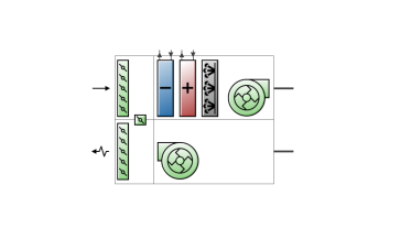
The basic generic AHU incorporates an outdoor air system and a supply fan. There are also options for night cycle operation, a heat recovery system, an economiser, pre-heat and pre-cool coils and an extract fan. Additional components such as heating coils, cooling coils and humidifiers may also be added to generic AHUs.
This is the name that you assign to the AHU which should be unique. If the supplied name is not unique, the software will automatically append a backslash and integer to ensure that there are no duplicate names.
This setting is used to indicate a Constant Air Volume (CAV) or Variable Air Volume (VAV) system. It can take one of two values:
Note 1: Once an air loop has been connected to a zone ADU, the Fan type setting is fixed (greyed out) preventing an invalid connection and remains greyed out until the air loop is disconnected from all ADUs.
Note 2: Once the AHU fan type has been set, the air loop containing the AHU can only be connected to valid zone air distribution units (ADU), i.e. CAV air loops can only be connected to CAV ADUs and similarly VAV systems can only be connected to VAV ADUs.
This is the air loop primary air design volumetric flow rate (in m3/s or ft3/min). This setting is auto-sizeable.
This is the schedule that contains information on the availability of the heat pump for operation. A schedule value greater than 0 (usually 1 is used) indicates that the unit can be on during the hour. A value less than or equal to 0 (usually 0 is used) denotes that the unit must be off for the hour.
This setting may be used to enable cycling of an air system when one or more zones become too hot or too cold. A common requirement for this mechanism is where the AHU is turned off at night. However if the building gets too cold there might be condensation on the walls and other damage. Thus the control system is usually programmed to turn the system on either if a specified control thermostat or any thermostat shows a zone temperature of less than a night time set point. Similarly, there might be a concern about a building getting too hot. Again the control system is programmed to turn the AHU back on if one or any zone temperature exceeds a night time cooling set point.
This mechanism offers considerable flexibility in determining how the night time on/off decision will be made. The temperature in one specific zone may be used or the temperatures in all the zones connected to the AHU may be sampled. You can specify a temperature tolerance and a run time for the system once it switches on. There is also an applicability schedule for scheduling when this mechanism may be applied.
This schedule determines whether or not for a given time period this mechanism is to be applied. Schedule values greater than zero (usually 1 is used) indicate the night cycle mechanism is to be applied, whereas schedule values less than or equal to zero (usually 0 is used) denote that it is not used for this time period.
The possible inputs are:
This is the amount (in °C or °F) by which the zone temperature must exceed the cooling set point or fall below the heating set point in order for the night cycle mechanism to signal that the system should turn on.
The time in seconds for which the system will run after it has cycled on. The default is 3600 seconds (1 hour).
For the Control Type option 3‑Cycle on control zone select the control zone.
An extract fan is included within all AHUs by default. This setting may be used to remove the extract fan from the AHU.
Note: If the AHU is connected to a zone that incorporates a Variable Air Volume with Reheat and Variable Speed Fan ADU, the AHU extract fan should be omitted otherwise EnergyPlus will raise an error and the simulation will be aborted.
The outdoor air system incorporates an air mixer, an optional pre-cool coil, an optional pre-heat coil, an optional heat recovery device and an outdoor air controller. The purpose of the outdoor air controller is to provide outdoor air for ventilation and also provide free cooling (through additional outdoor air and/or bypassing an air-to-air heat exchanger) whenever possible. The outdoor air controller includes a number of user-selectable limit controls. If any of the selected limits are exceeded, the outdoor airflow rate is set to the minimum.
If all the limits are satisfied, the outdoor air controller does the following for continuous air flow systems: if the outdoor air temperature is greater than or equal to the mixed air temperature setpoint, the outdoor air flow rate is set to the maximum; if the outdoor air temperature is less than the mixed air temperature setpoint, the outdoor air controller will modulate the outdoor air flow so that the mixed air temperature will match the mixed air setpoint temperature.
A time-of-day schedule may also be used to simulate an increase in outdoor air flow rate for “push-button” type economiser applications. When the schedule permits (i.e., schedule values are greater than 0), the outdoor air flow rate is increased to the user-specified maximum outdoor air flow rate.
The outdoor air controller can also account for changes in the outdoor air flow rate during times when indoor humidity levels are high. A zone humidistat must be used with this control option. During high indoor humidity, the outdoor air flow rate is modified in response to a high indoor humidity condition. If high humidity control is based on the outdoor air humidity ratio and the outdoor humidity ratio is greater than the indoor humidity ratio, high humidity control is terminated. When the economiser is used in conjunction with the high humidity control option, high humidity control has priority and controls the change in air flow rates. If the AHU Night Cycle option is switched on, it has priority over high humidity control and will use the controller’s maximum outdoor air flow rate when the Night Cycle mechanism cycles the fan on.
Optional pre-cool coil, pre-heat coil and heat recovery may be specified upstream of the mixer. When this is the case, any modulation will be determined by the conditions at the inlet node of the mixer rather than the outdoor air. This means that the controller will account for the heat recovery device or pre-heating/pre-cooling coils that may modify the condition of outdoor air before it reaches the mixer. If all the limits are satisfied, the outdoor air controller does the following for cycling fan systems: the outdoor air flow rate is set to the maximum when the fan cycles on. If the limits are not satisfied, the outdoor air flow rate is at the minimum when the fan cycles on.
This is a read-only label that is automatically generated by the software and which incorporates the name of the air loop in which the AHU is located.
If this option is checked, the AHU will re-circulate a proportion of the air delivered by the AHU, otherwise the system will operate as a 100% fresh air system.
This is the minimum outdoor air flow rate for the system (in m3/s).
Choices for this field are:
Options for an economiser are:
In addition to all economiser control types listed above, each control type checks for user-entered values for the upper limit of dry-bulb temperature, enthalpy limit, humidity ratio limit and dew-point limit. The outdoor air flow rate is set to minimum if any of these entered limits are exceeded.
This is the maximum outdoor air flow rate for the system (in m3/s or ft3/min).
There are two choices:
The second option 2‑Minimum flow with bypass is only available if Heat Recovery is selected. If 1‑Modulate flow is selected, this means that the outdoor air flow rate will be increased to meet the mixed air setpoint temperature, subject to the limits imposed via other inputs for this object (e.g., Economizer Maximum Limit Dry-Bulb Temperature, Maximum Outdoor Air Flow Rate, etc.). The 2‑Minimum flow with bypass option is used in conjunction with a heat recovery device for providing free cooling operation in the absence of a conventional air-side economizer (i.e., when outdoor air flow rate is not increased during economizer mode). The 2‑Minimum flow with bypass choice forces the outdoor air flow rate to always remain at the minimum. However, when high humidity control is used, the outdoor air flow rate is set to the product of the maximum outdoor air flow rate multiplied by the high humidity outdoor air flow ratio. The heat exchanger uses the limit checking in the outdoor air controller to decide whether or not to bypass the outdoor air around the heat exchanger – or turn off the wheel motor in the case of a rotary heat exchanger. Heat exchange is also suspended when high humidity control is active.
This option is only available for Unitary Heat Cool or Unitary Heat Pump AHUs. Choices for this setting are:
This is an optional outdoor air temperature low limit (in °C or °F) for economiser operation. If the outdoor air temperature is below this limit, the outdoor airflow rate will be set to the minimum. This limit applies to the conditions at the Actuator Node regardless of whether or not there are any other components in the outdoor air path upstream of the mixer.
This is an optional outdoor air temperature high limit (in °C or °F) for economiser operation. If the outdoor air temperature is above this limit, the outdoor airflow rate will be set to the minimum. This limit applies to the conditions at the Actuator Node regardless of whether or not there are any other components in the outdoor air path upstream of the mixer.
This is an optional outdoor air enthalpy limit (in J/kg or Btu/lb) for economiser operation. If the outdoor air enthalpy is above this value, the outdoor airflow rate will be set to the minimum. This field is required if the Economiser type is set to 4‑Fixed enthalpy. This limit applies to the conditions at the Actuator Node regardless of whether or not there are any other components in the outdoor air path upstream of the mixer.
This is an optional outdoor air dew-point limit (in °C or °F) for economiser operation. If the outdoor air dew-point temperature is above this value, the outdoor airflow rate will be set to the minimum. This limit applies to the conditions at the Actuator Node regardless of whether or not there are any other components in the outdoor air path upstream of the mixer.
This is an optional Quadratic or Cubic curve which provides the maximum outdoor air humidity ratio (function of outdoor air dry-bulb temperature) for economiser operation. If the outdoor air humidity ratio is greater than the curve’s maximum humidity ratio (evaluated at the outdoor air dry-bulb temperature), the outdoor air flow rate will be set to the minimum. This limit applies to the conditions at the Actuator node regardless of whether or not there are any other components in the outdoor air path upstream of the mixer.
This is an optional schedule which controls the outdoor air flow rate based on a time-of-day economiser. Schedule values equal to 0 disable this feature. A schedule value of greater than 0 causes the outdoor air flow rate to increase to the maximum. When an economiser is used in conjunction with the high humidity control option, high humidity control has priority.
This setting establishes whether or not the outdoor air flow rate is modified in response to high indoor relative humidity. If 2‑Yes is selected, the outdoor air flow rate may be modified when the indoor relative humidity is above the humidistat setpoint. If 1‑No is selected, this option is disabled and the following three settings are not displayed.
This is the zone name where the humidistat is located. This setting is only required when the High Humidity Control is set to 2‑Yes.
This is the ratio of the modified outdoor air flow rate to the maximum outdoor air flow rate. When the high humidity control algorithm determines that the outdoor air flow rate will be changed (i.e. increased or decreased), the operating outdoor air flow rate is equal to the maximum outdoor air flow rate multiplied by this ratio. The minimum value for this setting is 0. This setting is only required when the High humidity control is set to 2‑Yes. When an economiser is used in conjunction with the high humidity control option, high humidity control has priority.
This setting determines if high humidity control is activated based on high indoor relative humidity alone or is activated only when the indoor relative humidity is above the humidistat setpoint and the indoor humidity ratio is greater than the outdoor humidity ratio. Valid choices are 1‑Yes and 2‑No. If 2‑No is selected, high humidity control is active any time the zone humidistat senses a moisture load. If 1‑Yes is selected, the model also verifies that the outdoor humidity ratio is less than the humidistat’s zone air humidity ratio. This setting is only required when the High Humidity Control is set to 2‑Yes.
This is an optional schedule which uses decimal values (0.0 – 1.0). These values are multiplied by the minimum outdoor air flow rate. This schedule is useful for reducing the outdoor air flow rate to zero during unoccupied or start up hours. If this schedule option is not used, the minimum outdoor air flow rate either remains constant during the simulation period (Minimum limit type = 2‑Fixed minimum) or varies in proportion to the supply air flow rate (Minimum limit type = 1‑Proportional minimum).
This is an optional schedule which uses decimal values (0.0 – 1.0). These values are multiplied by the total (design) air flow rate. This is an alternate method for specifying the minimum outdoor air amount. The other method is the Minimum outdoor air schedule described above.
Note: This setting overrides Outdoor air flow rate.
This is an optional schedule with values in decimal fractions (0.0-1.0). This setting enables you to limit the maximum amount of outdoor air permissible and thus also limits the permissible maximum outdoor air into the system.
If this option is checked, the AHU will incorporate a sensible and latent air-to-air heat recovery device capable of both heating and cooling the supply air stream using waste energy from the exhaust side.
Heat exchanger performance can be specified to transfer sensible energy, latent energy or both between the supply and exhaust air streams. The input requires no geometric data. Performance is defined by specifying sensible and/or latent effectiveness at 75% and 100% of the nominal (rated) supply air flow rate at two operating conditions as shown in the following table:
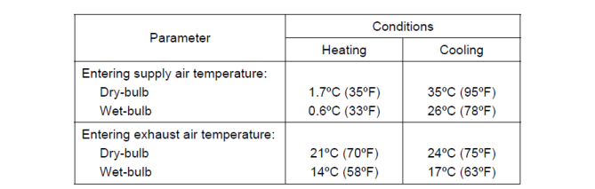
Operating Conditions for Defining Heat Exchanger Performance.
Note: Conditions consistent with the Air-Conditioning and Refrigeration
Institute’s (ARI) Standard 1060-2001
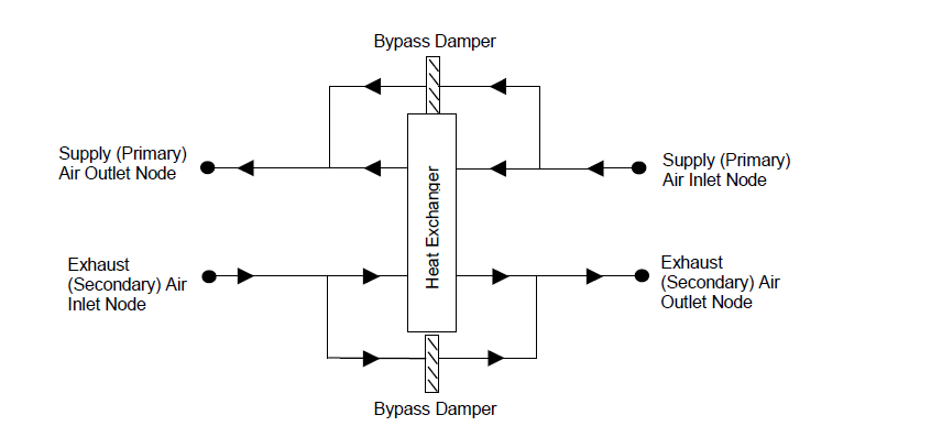
Heat exchange between the supply and exhaust air streams occurs whenever the unit is scheduled to be available (Availability schedule) and supply/exhaust air flow is present. Heat recovery can be used in conjunction with a conventional air-side economiser (select 1‑Modulate flow for the Economiser control action type), whereby heat exchange is suspended whenever the air-side economiser (or high humidity control) is active (i.e. air flow is fully by-passed around a fixed-plate heat exchanger or the rotation of a rotary heat exchanger is stopped). It is also possible to suspend heat exchange for the purpose of providing free cooling operation in the absence of a conventional air-side economizer (i.e. specify 2‑Minimum flow with bypass for the Economiser control action type). During winter weather, humid exhaust air entering the heat exchanger can form frost on the cold heat exchanger surfaces, which can reduce air flow and the amount of energy recovery. Several methods are used to control or eliminate frost formation, and the following types can be modelled for this heat exchanger object: supply air pre-heat, minimum exhaust air temperature, exhaust air recirculation and exhaust only. For preheat frost control, the Pre-heat Coil option must be checked under the Pre-Treatment header. The other frost control types may be selected using the Frost control type drop-list.
Air-to-air heat exchangers are sometimes controlled to maintain a fixed supply air outlet temperature to avoid overheating. To model this control in EnergyPlus, a Setpoint manager is used to establish a temperature set point at the supply air outlet node of the heat exchanger. Wheel speed modulation or plate supply air bypass is used to control the supply air exiting conditions to this set point. The set point for supply air temperature control should be set at the minimum economizer temperature set point if an air-side economizer is also being used by the air system. If frost control and supply air outlet temperature control are used, frost control takes precedence over supply air temperature control (e.g. Control defrost time fraction is determined as if wheel speed modulation or plate supply air bypass is not used).
The nominal primary side (supply) air flow rate (in m3/s or ft3/min). The actual supply and exhaust air flow rates must be between 50% and 130% of this value or a warning will be issued.
This is the electric consumption rate of the device (W). Electric power is considered constant whenever the unit operates. This numeric input can be used to model electric power consumption by controls (transformers, relays, etc.) and/or a motor for a rotary heat exchanger. None of this electric power contributes thermal load to the supply or exhaust air streams. The default value for this field is 0.
This alpha field determines if the heat exchanger’s supply air outlet is controlled to a temperature set point. The choices for this input field are 1-Yes or 2-No, with the default being 2-No. When supply air outlet temperature control is used, the wheel rotational speed modulates or supply air is bypassed around the plate heat exchanger to maintain the desired setpoint temperature. A Setpoint manager is required to establish the desired set point at the supply air outlet node. When an air-side economizer is also being modelled for this air system, the set point for the supply air outlet temperature control should be equal to the Economizer minimum limit dry-bulb temperature.
This setting is used to define the type of heat exchanger being modelled. The options are:
The heat exchanger type affects the modelling of frost control options and supply air outlet temperature control. For rotary heat exchangers, rotational speed is varied to control frost formation or the supply air outlet temperature. For plate exchangers, air bypass around the heat exchanger is used to obtain the desired effect.
This input denotes whether the heat exchanger unit is locked out (bypassed for plate type heat exchangers or the rotation is suspended for rotary type heat exchangers) when the air-side economiser is operating. Both the economiser and High Humidity Control activate the heat exchanger lockout as specified by this input. The input choices are 1‑Yes (meaning locked out) or 2‑No.
The sensible heat exchange effectiveness at the heating condition defined in the Table above with both the supply and exhaust air volume flow rates equal to 100% of the nominal supply air flow rate specified in the previous input field. The default value for this field is 0.
The latent heat exchange effectiveness at the heating condition defined in the Operating Conditions for Defining Heat Exchanger Performance table with both the supply and exhaust air volume flow rates equal to 100% of the nominal supply air flow rate. Specify this value as 0.0 if the heat exchanger does not transfer latent energy. The default value for this field is 0.
The sensible heat exchange effectiveness at the heating condition defined in the Operating Conditions for Defining Heat Exchanger Performance table with both the supply and exhaust air volume flow rates equal to 75% of the nominal supply air flow rate. The default value for this field is 0.
The latent heat exchange effectiveness at the heating condition defined in the Operating Conditions for Defining Heat Exchanger Performance table with both the supply and exhaust air volume flow rates equal to 75% of the nominal supply air flow rate. Specify this value as 0.0 if the heat exchanger does not transfer latent energy. The default value for this field is 0.
The sensible heat exchange effectiveness at the cooling condition defined in the Operating Conditions for Defining Heat Exchanger Performance table with both the supply and exhaust air volume flow rates equal to 100% of the nominal supply air flow rate. The default value for this setting is 0.
The latent heat exchange effectiveness at the cooling condition defined in the Operating Conditions for Defining Heat Exchanger Performance table with both the supply and exhaust air volume flow rates equal to 100% of the nominal supply air flow rate. Specify this value as 0.0 if the heat exchanger does not transfer latent energy. The default value for this setting is 0.
The sensible heat exchange effectiveness at the cooling condition defined in the Operating Conditions for Defining Heat Exchanger Performance table with both the supply and exhaust air volume flow rates equal to 75% of the nominal supply air flow rate. The default value for this setting is 0.
The latent heat exchange effectiveness at the cooling condition defined in the Operating Conditions for Defining Heat Exchanger Performance table with both the supply and exhaust air volume flow rates equal to 75% of the nominal supply air flow rate. Specify this value as 0.0 if the heat exchanger does not transfer latent energy. The default value for this field is 0.
There are four options for frost control:
If a pre-heat frost control coil is specified, this setting is automatically set to 1‑None and disabled.
This numeric field defines the dry-bulb temperature of air which is used to initiate frost control (in °C or °F). The default value is 1.7ºC. If 2‑Exhaust air recirculation or 3‑Exhaust only options are selected the Frost control type, the threshold temperature defines the supply (outdoor) air inlet temperature below which frost control is active. For 4‑Minimum exhaust temperature frost control, heat exchanger effectiveness is controlled to keep the exhaust air outlet temperature from falling below this threshold temperature value.
The appropriate threshold temperature varies with exhaust (inlet) air temperature and humidity, frost control type, heat exchanger type, and whether the heat exchanger transfers sensible energy alone or both sensible and latent energy (enthalpy). Typical threshold temperatures are provided in the table below. However, it is recommended that the user consult manufacturer’s information for the specific air-to-air heat exchanger being modelled.
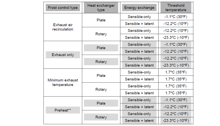
Typical Threshold Temperatures
Source: Indoor Humidity Assessment Tool, U.S. Environmental Protection Agency,
** To model preheat frost control, specify frost control type as 1‑None and select a pre-heat coil for the AHU controlled to the keep the air temperature above the frost threshold temperature.
This is the fraction of the simulation timestep when frost control will be invoked when the threshold temperature is reached. This setting is only used for the 2‑Exhaust air recirculation and 3‑Exhaust only frost control types. The value for this setting must be ≥ 0 and ≤ 1. The default time fraction is 0.083 (e.g., 5 min / 60 min) which is typical for Exhaust air recirculation frost control. Higher initial defrost time fractions (e.g., 0.167 = 10 min / 60 min) are typically required for Exhaust only frost control. For best results, you should obtain this information from the manufacturer.
This is the rate of increase in the defrost time fraction as the supply (outdoor) air inlet temperature falls below the threshold temperature. This field is only used for the 2‑Exhaust air recirculation and 3‑Exhaust only frost control types. The value for this setting must be ≥ 0. The default value is 0.012 (e.g., 0.72 min / 60 min per degree C temperature difference) which is typical for Exhaust air recirculation frost control. Higher values (e.g. 0.024 = 1.44 min / 60 min per °C temperature difference) are typically required for Exhaust only frost control. For best results, you should obtain this information from the manufacturer.
The total defrost time fraction is determined as follows:
Total defrost time fraction = Initial Defrost Time Fraction + Rate of Defrost Time Fraction Increase * (Tthreshold – Tsupply air inlet)
The model does not allow the total defrost time fraction to exceed 1.0 or be less than 0.
This is the schedule that determines whether or not the heat recovery device is available for each timestep of the simulation. A schedule value greater than 0 (usually 1 is used) indicates that the device can be on. A value less than or equal to 0 (usually 0 is used) denotes that the device must be off.
This setting allows you to add a pre-heat coil to the air handling unit.
The schedule value for each time period is the setpoint for the off-coil temperature (in °C only).
This setting allows you to add a pre-cool coil to the air handling unit.
The schedule value for each time period is the setpoint for the off-coil temperature (in °C only).